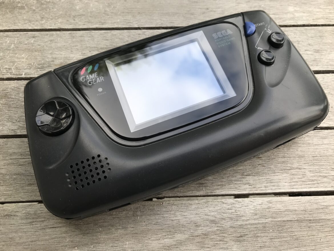
In this post I write some notes about fixing a Game Gear with a very dark screen. The dark screen is one of the symtoms of failing capacitors in the console. This is a common problem with the Game Gear, and the procedure to replace the capacitors is pretty straight forward, although challenging in my experience, as I will further describe below.
Step 1: Disassemble the Game Gear
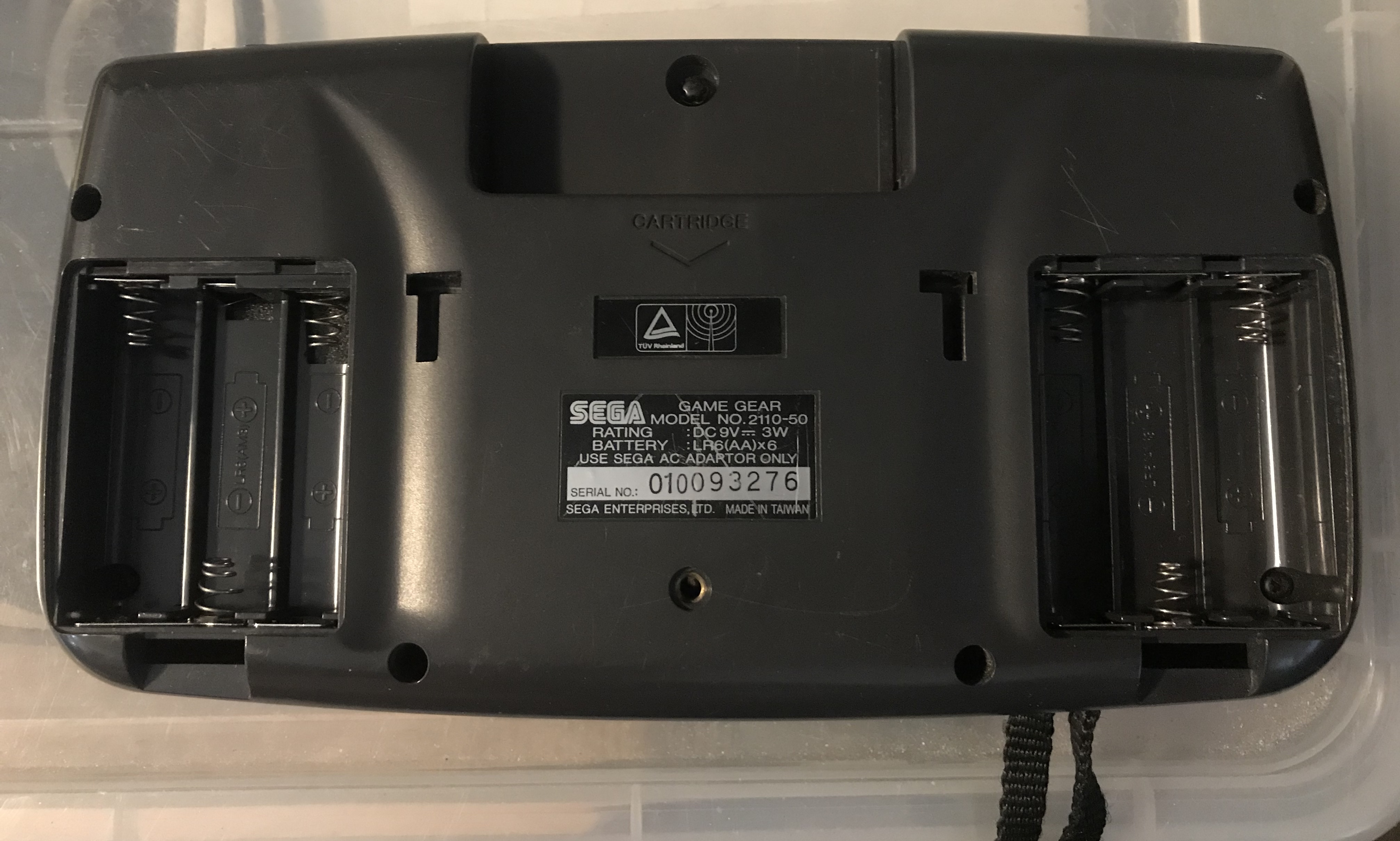
To disassembly the SEGA Game Gear you need a regular Philips screw driver, and a Gamebit screwdriver (this is the same type of screwdriver you use for other consoles as well, such as NES, SNES and Gameboy). There are a total of six regular screws (including one in each battery compartment), and one Gamebit screw in the cartridge slot.
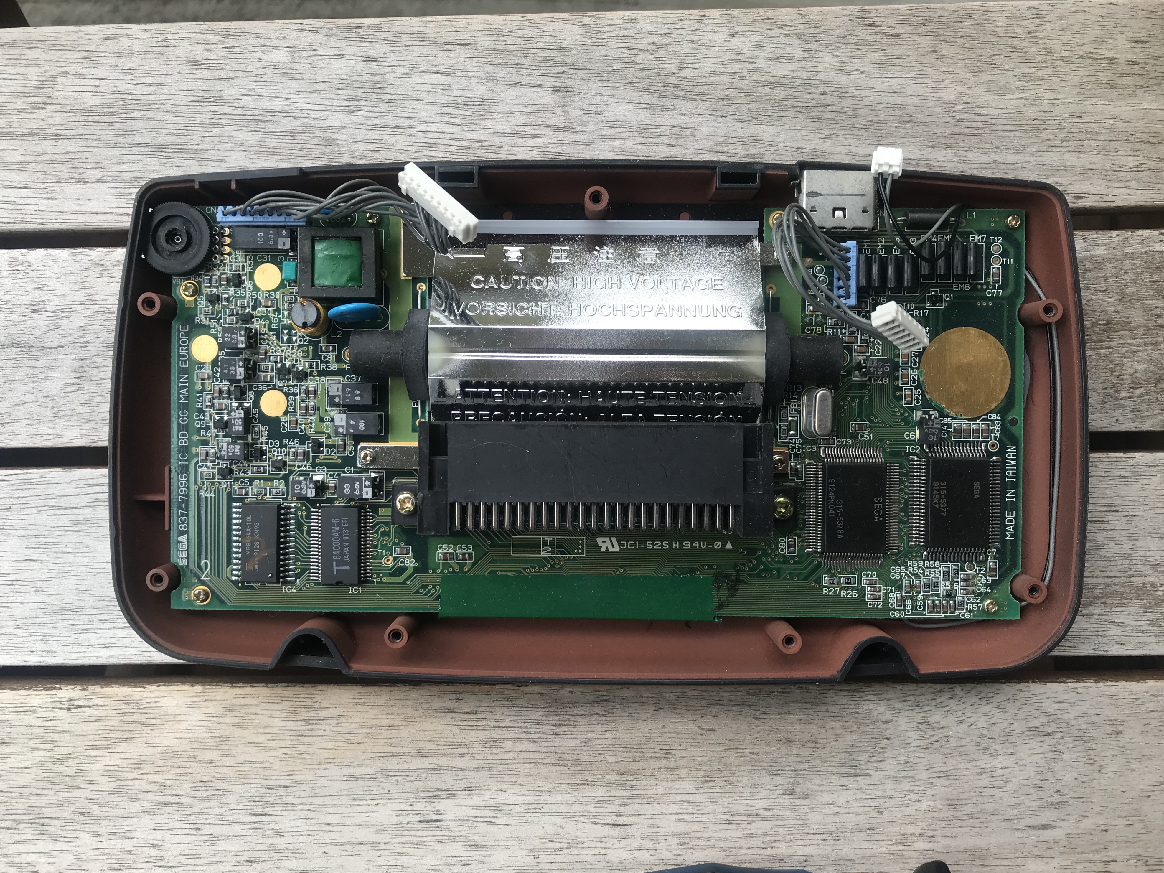
The Game Gear essentially consists of three boards: The main board, the power board, and the audio board. These are connected through three cables, which you should disconnect to separate the two parts of the housing. Disattach the _white_ part of the cables from the power- and audio board.
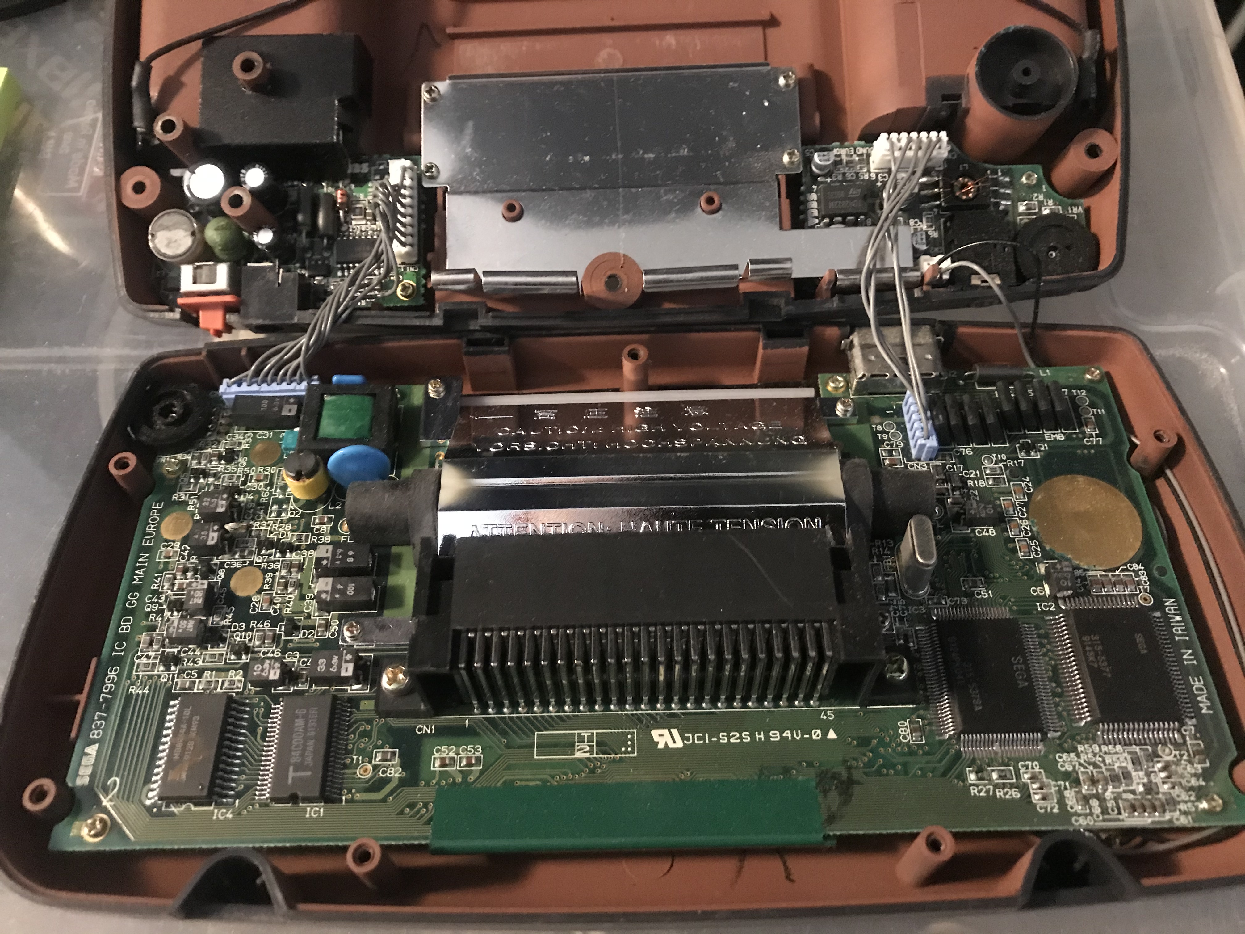
Now you can remove the main board from the housing. To do so, remove the Philips screws from the main board. There are a total of 10 screws to remove, 8 small and 2 big (next to the cartridge connector).
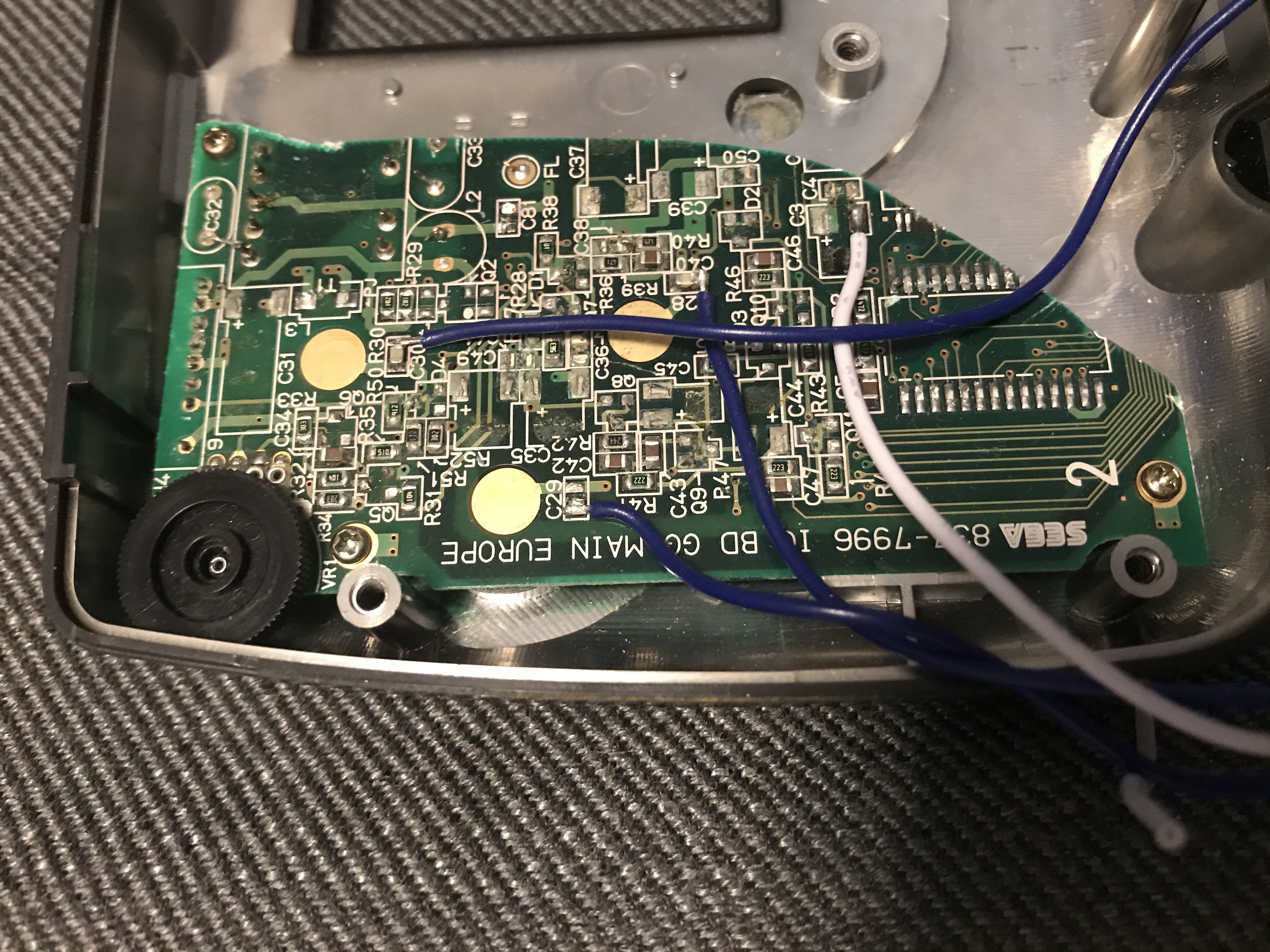
Step 2: Identify the model of your Game Gear
Now, it is time to identiify what model your particular Game Gear is, in order to buy the correct capacitors. I used the site below to identify my boards:
Main Board:
https://console5.com/techwiki/images/a/a7/Game-Gear-VA1—2-ASIC.png
Audio + Power board:
https://console5.com/techwiki/images/b/b5/Game-Gear-Power-Sound.png
Capacitor list for my Game Gear:
Main board:
C1 33uF 6.3V
C3 10uF 6.3V
C6 10uF 6.3V
C31 100uF 6.3V
C35 4.7uF 35V
C37 68uF 6.3V
C39 100uF 4V
C44 0.47uF 50V
C45 0.47uF 50V
C48 10uF 6.3V
C49 22uF 6.3V
Power board:
C5 22uF 35v
C11 100uF 25v
VC13 820uF 6.3v
Audio board:
C1 100uF 6.3V
C2 100uF 6.3V
C3 100uF 6.3V
C5 47uF 4V
C7 47uF 4V
Many of the new capacitors I bought have higher voltages than the original ones, which is fine as long as the Farad (uF) is the same. The voltage of the replacement capacitors should _not_ go below the original ones though.
Step 3: Desolder the old capacitors
Be _very_ careful when desoldering the old capacitors. This might be tricky since they might have leaked and damaged the solder pads. Worst case is that the solder pads are ruined and you will have anything to solder the new capacitor to.
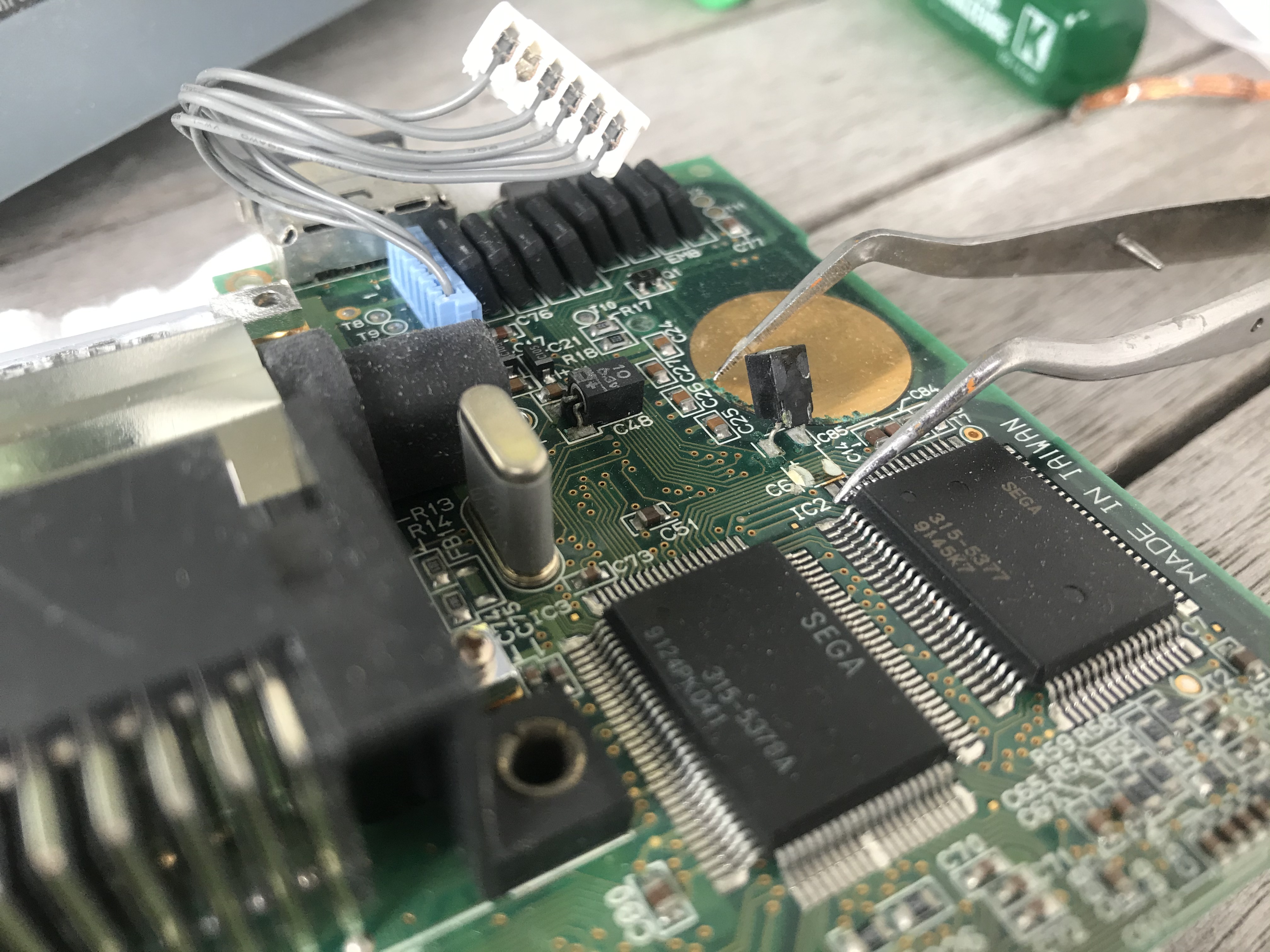
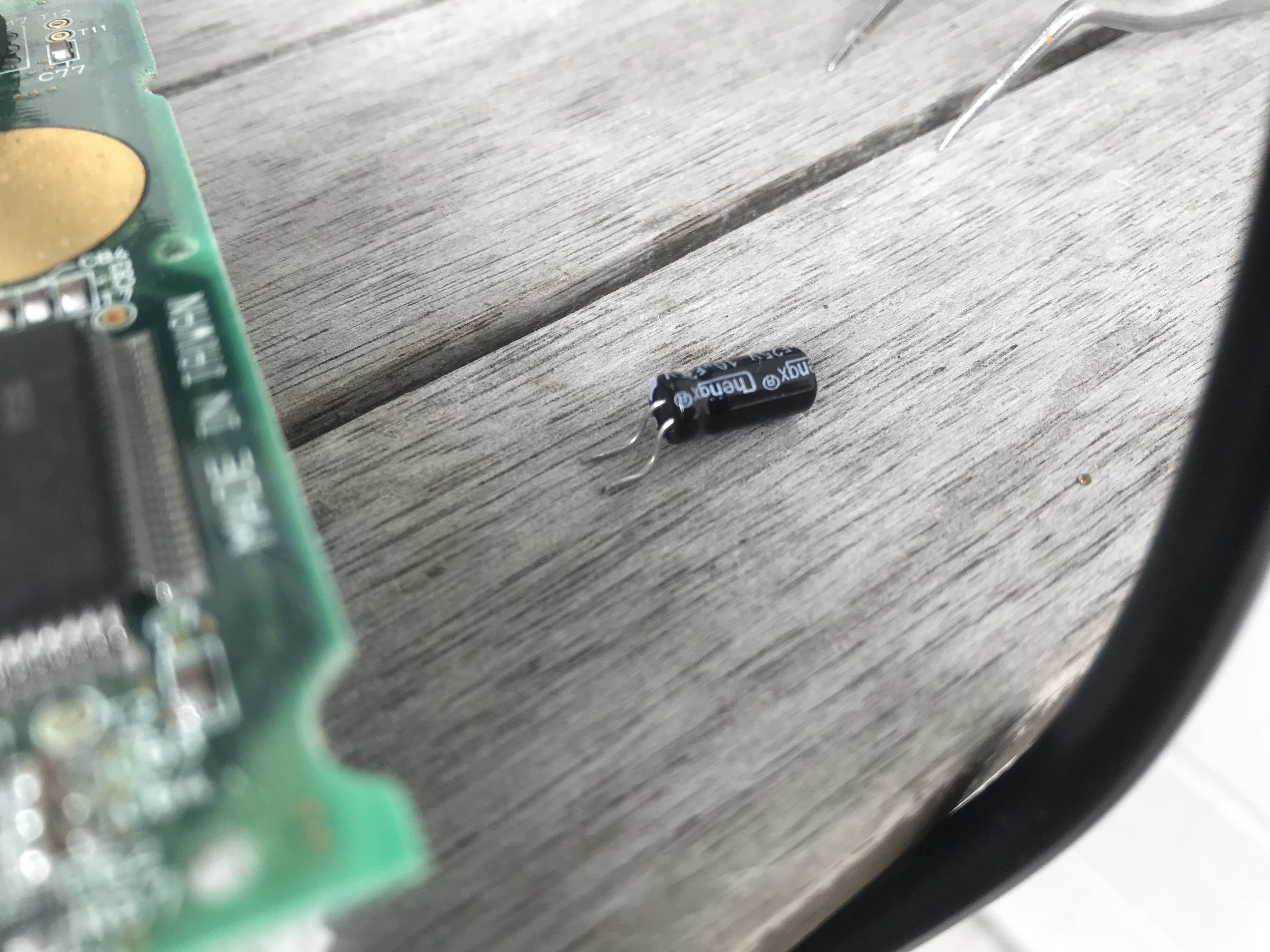
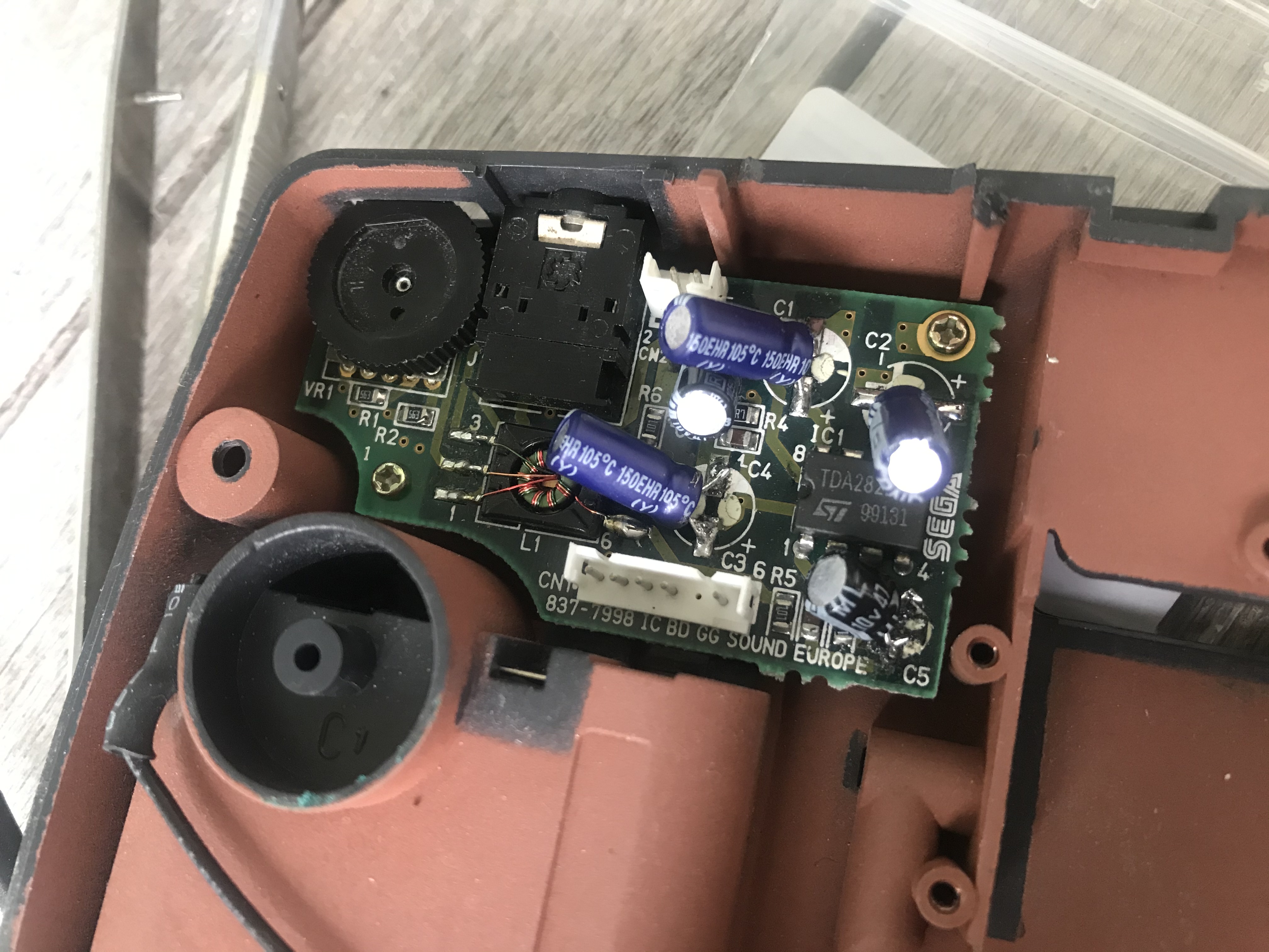
To remove the capacitors from the main board, pry them gently up with a pair of tweezers (they are glued to the board). Then add some solder on the legs, heat them up, and lift them off.
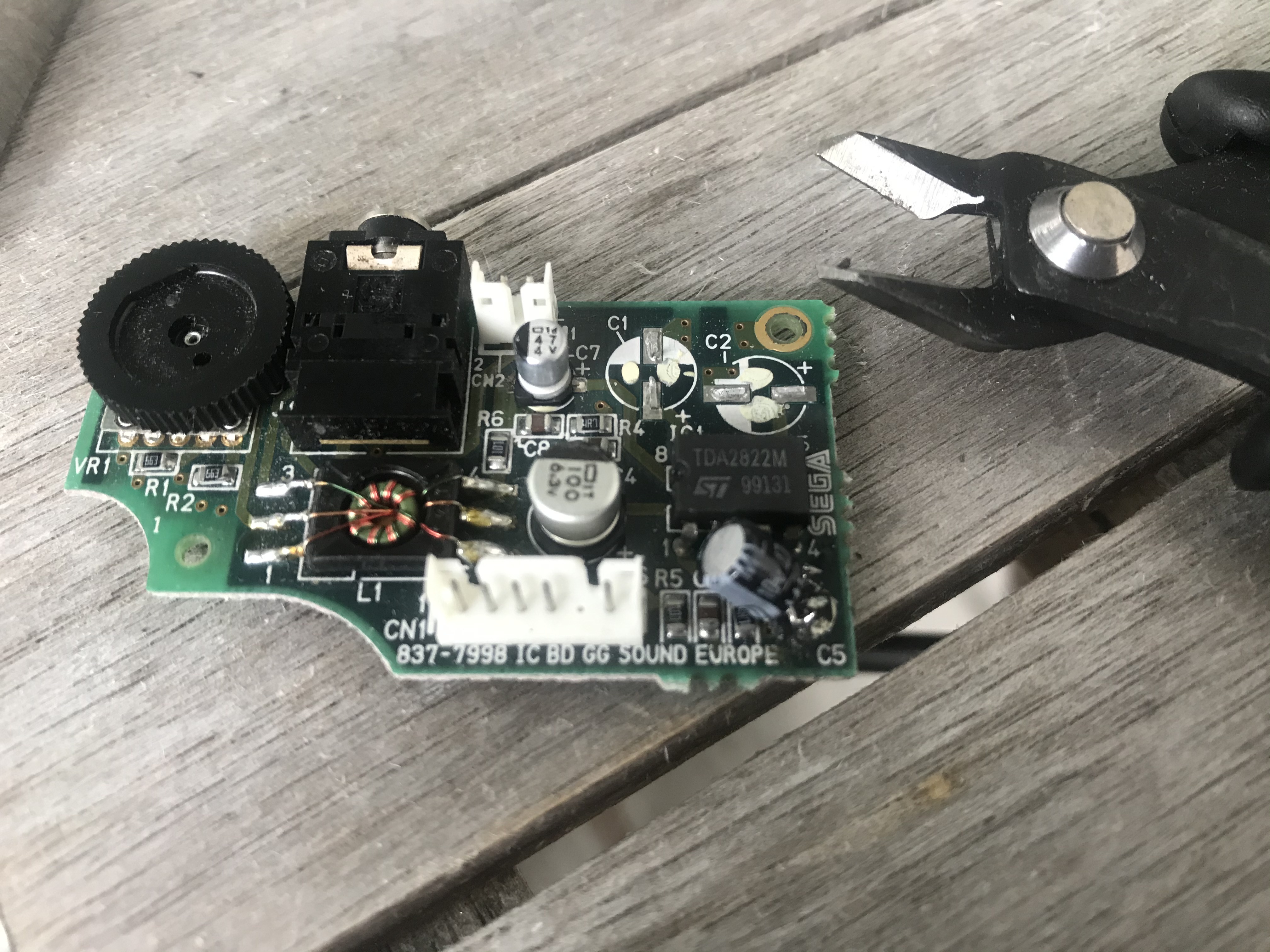
The capacitors on the audio board are of a surface mount type. The easiest way to remove these was to (gently!) snip the legs of with a cutter, remove residue, desolder the legs, and add new solder onto the solder pads.
Step 4: Add the new capacitors
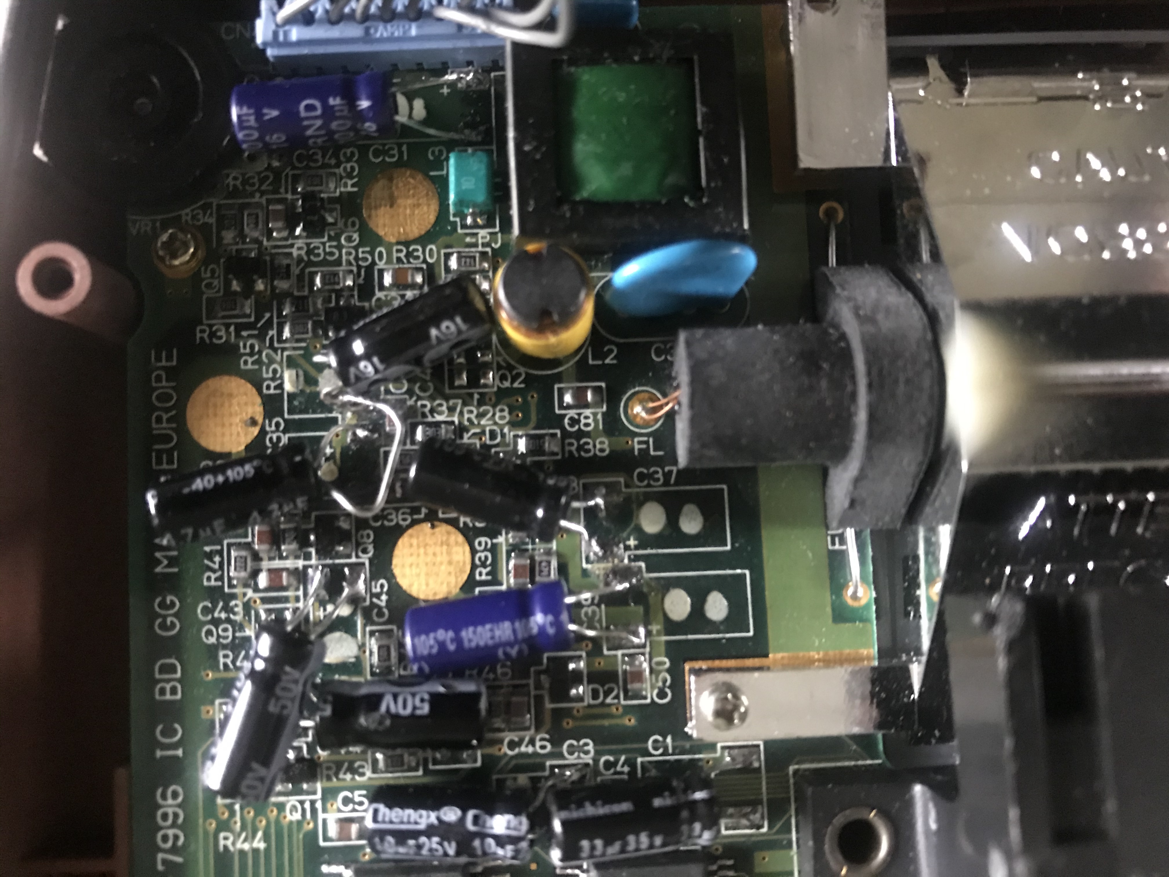
It is time to solder the new capacitors to your Game Gear. Of course you may also do step 3 and 4 at the same time, replacing the capacitors one by one. I cut and bent the capacitor legs on most of the components as shown in the image below.
I ran into some tricky situation on several spots on the main board where the old capacitors had leaked and there was almost nothing left of the solder pad to attach the new capacitor to. In some instances I had to guess whether I was actually soldering the capacitor to something, or if I was simply “gluing” it to the board with the soldering iron. In one case I had to share the negative leg of two capacitors (c35 and c49) since there was nothing to solder c35’s negative leg to. Luckily it goes to common ground, which is also the case with c49. In the end, everything went fine though.
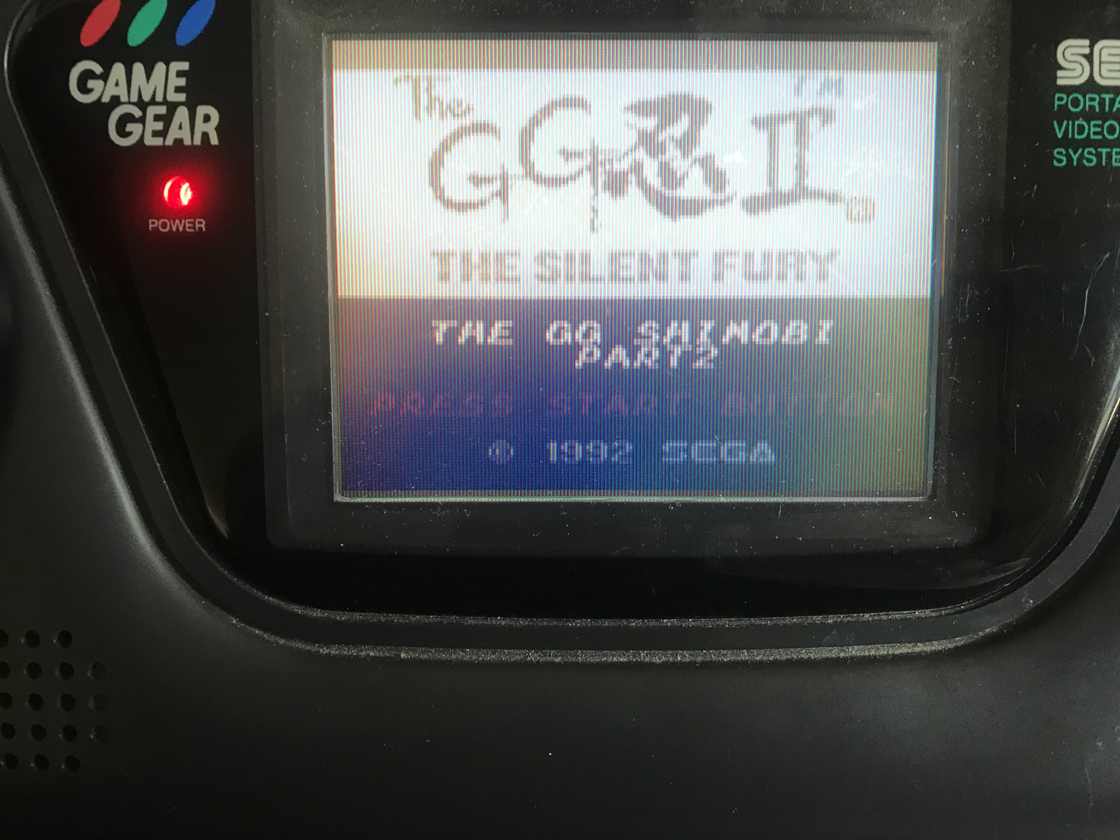
I booted up NHL All-Star Hockey, and good image, but no sound. So I proceeded with replacing the capacitors on the audio board (see step 3 for how to desolder these).
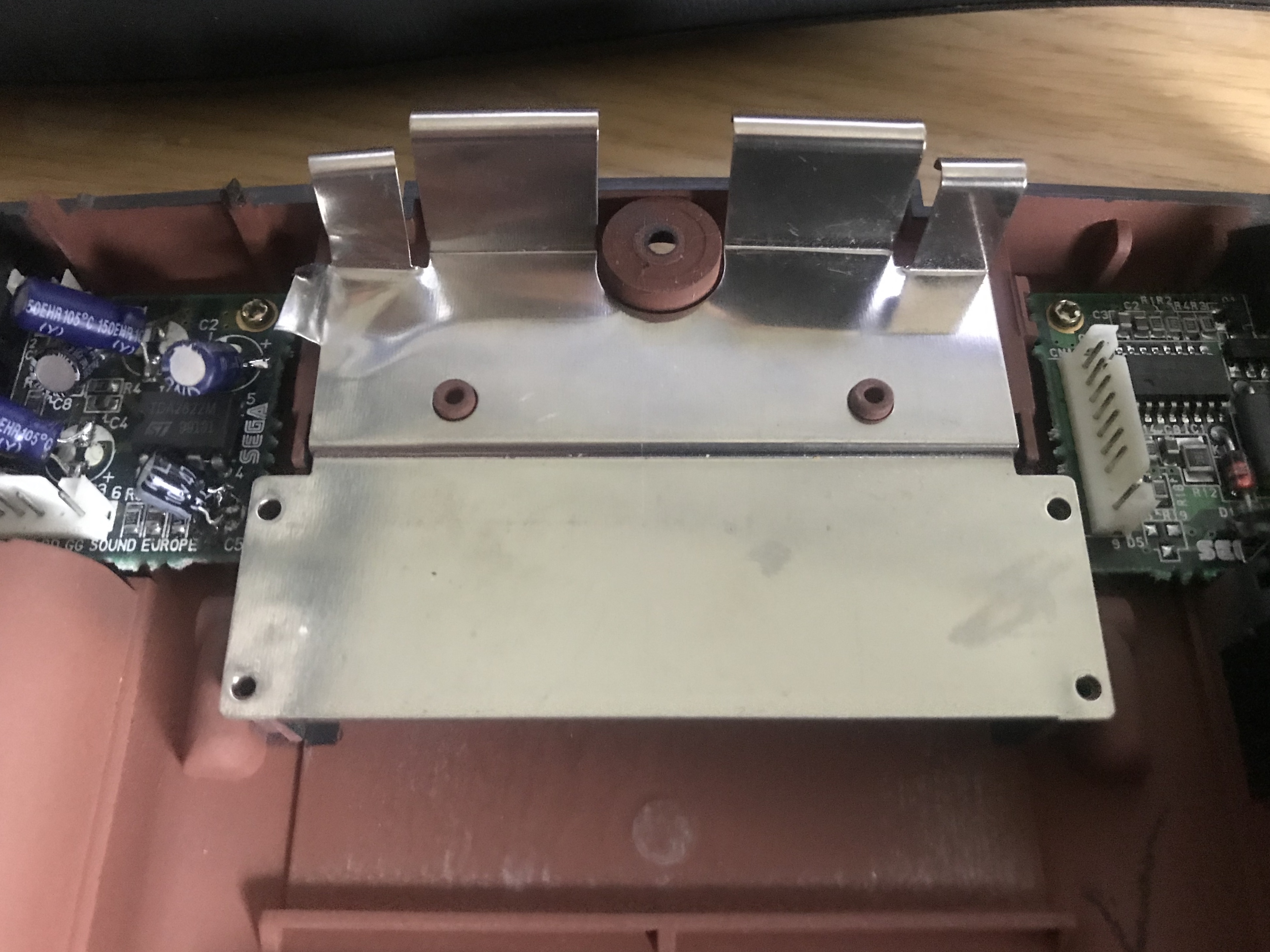
The new capacitors take up more room than the old ones, so I had to cut a piece of the metal shielding to make them fit. Now, the audio worked as well!

I did not change the capacitors in the power board yet, but will probably do this in due time. Meanwhile, I will enjoy playing Game Gear games on original hardware.
This post continues with an overview of a small project I have been working on: a Raspberry Pi in a SEGA Game Gear shell.
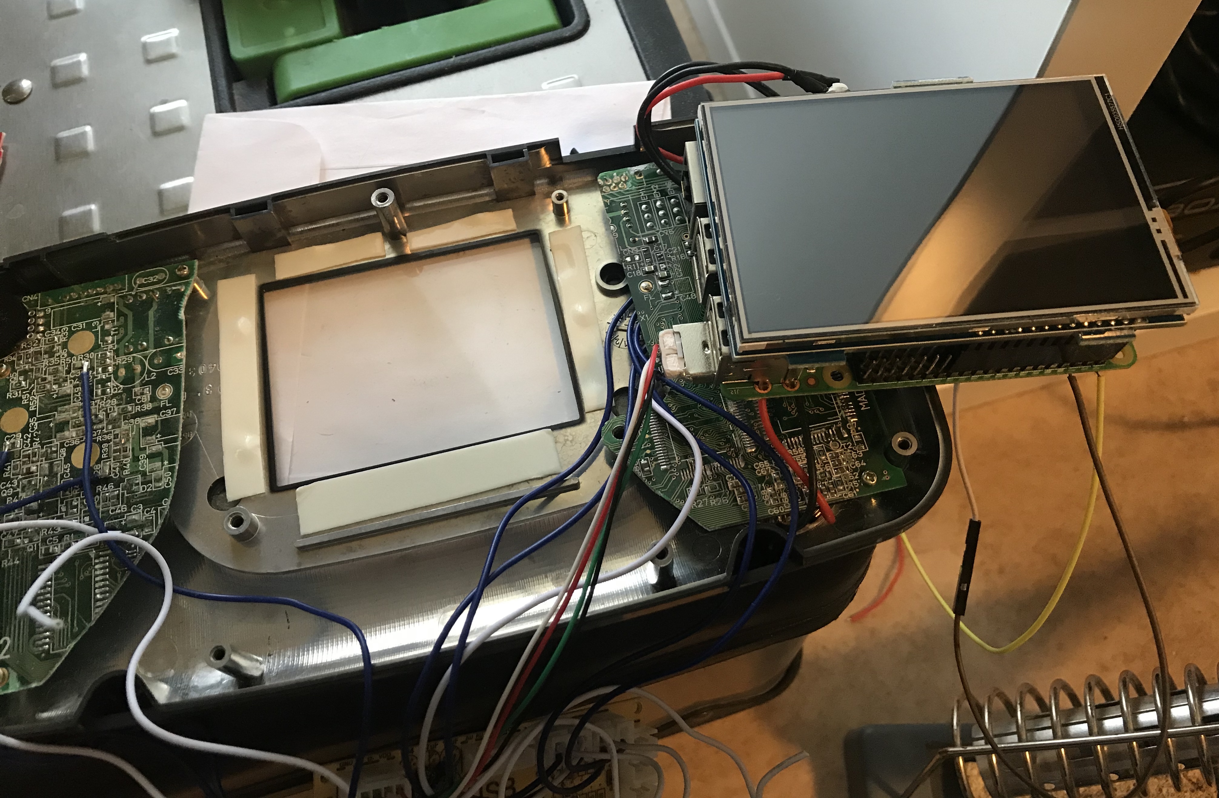
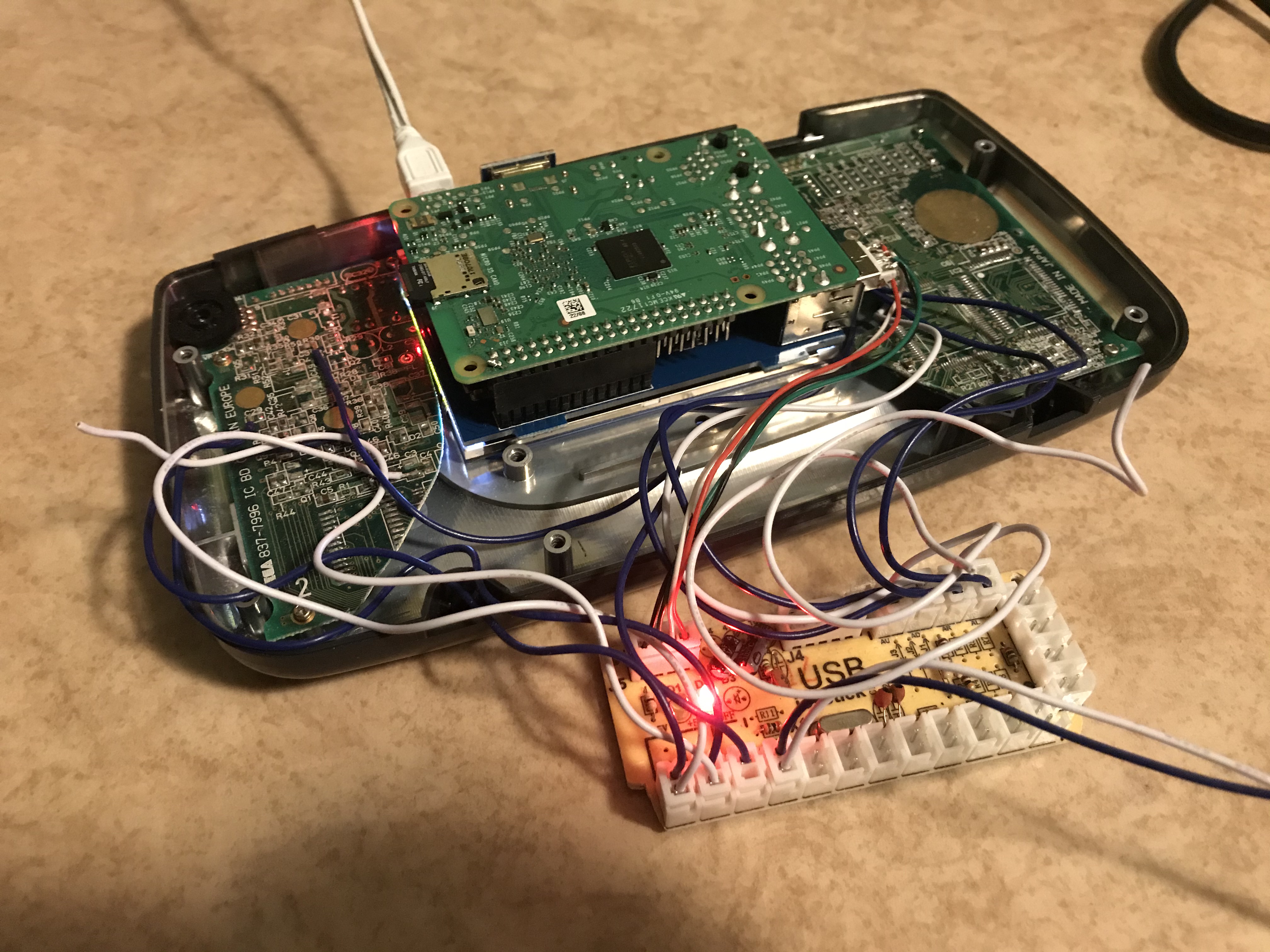
Game Gear Pi
Sometimes a game console is broken beyond repair, which was the case with a Game Gear I bought. I decided to convert it into an 8-bit gaming machine by adding Raspberry Pi + LCD-screen into it, while keeping the original Game Gear controller buttons through the use of a USB joystick board as seen below. I also added a fourth button, which I think is a minimum for running Retropie. For sound, I use a small Chinese amplifier between the 3.5 mm output of the pi and the original Game Gear speaker.
For 8-bit consoles, a Pi zero might be more optimal than the RP3, especially if I would like to run it on battery power. Currently, I have to use an AC adapter, which is a drawback for a portable project. This is a work in progress, and I will write updates when I perform additional changes.