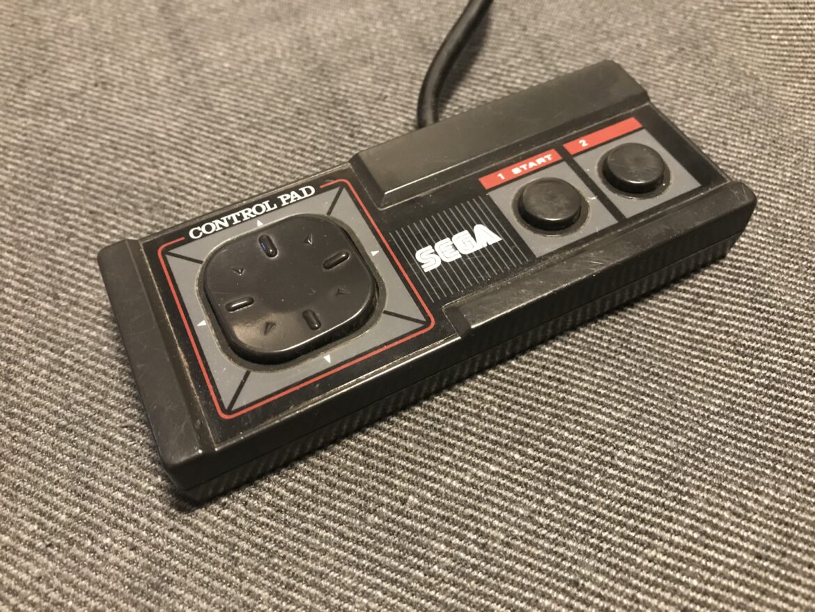
Like any other old controller, the SEGA Master System gamepad can be worn over time, which causes faults such as non-responsive buttons, or directions on the d-pad to stop working. One of my controllers would not react when I pressed up on the d-pad, and in this post I will describe how I repaired it.
Disassembly the SEGA Master System controller
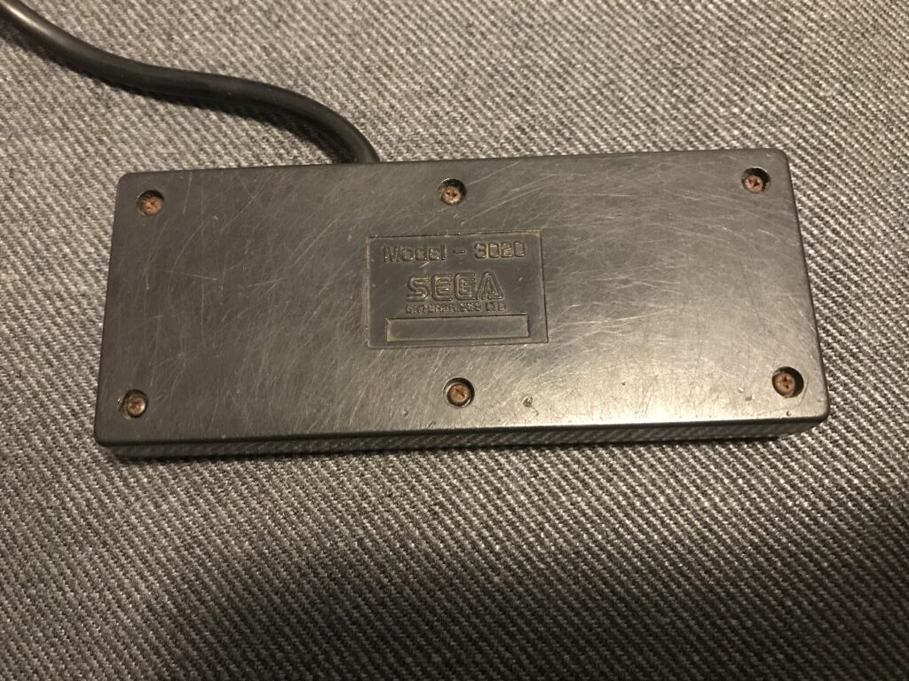
To disassembly the controller, simply remove the 6x philips screws on the back.
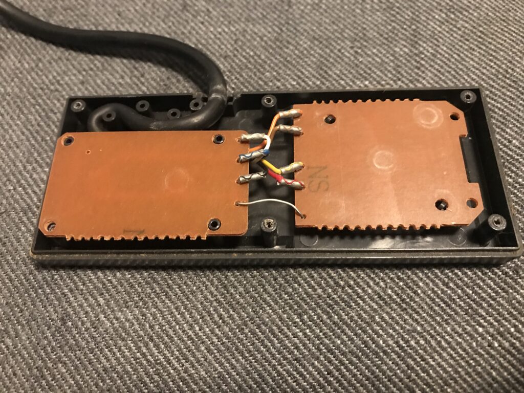
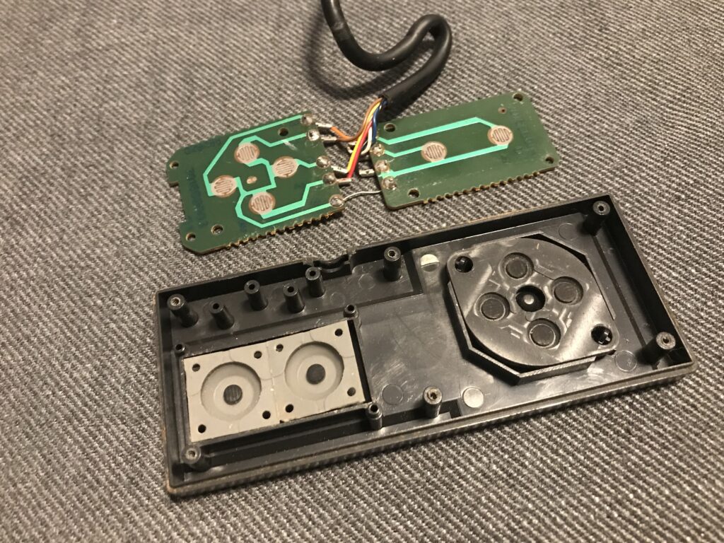
Now, the inside of the controller is revealed, as shown below. The design is rather straight-forward, with a couple of pcb:s connected to the cable, and three rubber pads (d-pad, 2x buttons). Now is a good opportunity to check the condition of the rubber pads, and give the controller a good clean with some isopropanol alcohol. However, just cleaning the controller did not help in my case. The d-pad “up” is non-responsive, and I suspected a cable break. The only way to solve this is by replacing the cable.
Replace the SEGA Master System controller cable
To make sure it is really the cable that is at fault, you should use a multimeter in continuity mode, and measure between the end of the cable with the connector, and the respective points at the pcb:s. Now you will also achieve an idea of which cable that corresponds to what button. This is important for when you have to replace the cable. Also, check this guide for a good overview of the button layout of the controller.
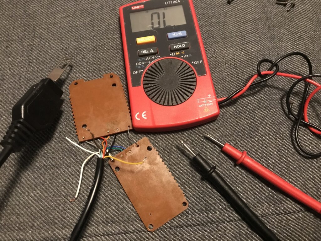
If you notice lost continuity on any button or direction, is it time to replace the cable. When you buy a new cable on eBay for example, the cable colors might be different. Cut the cable and use the multimeter together with the above link of the gamepad layout to determine what color goes to what. I could use my scheme from when I repaired the Wico Q stick joystick in a previous post to identify button 1 + up / down / left / right, followed by placing the multimeter in pin 9 to see what cable color button 2 had (as seen below, it was yellow).
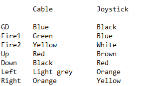
Now, cut away the old wires from the pcb:s. Solder the wires from the new cable to the pcb (similar to how I did with the Wico Q stick seen in the link above). I used my joystick tester to make sure everything was in order before assembling the controller (my joystick tester does not detect button 2, so I test that button on the Master System itself). Happy (retro) gaming!
